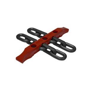
G80 3mm and 2mm Galvanised Lashing Chain High Tensile Alloy Steel Lifting Link Chain for Electric Hoist
G80 3mm and 2mm Galvanised Lashing Chain High Tensile Alloy Steel Lifting Link Chain for Electric Hoist
Category
Lifting and lashing, hoisting chain,short link chain, round link chain lifting,Grade T chain, Grade DAT chain,Grade DT chain, DIN EN 818-7short link chain for lifting purposes,fine tolerance hoist chain,alloy steel chain
Application
Lifting and lashing, loads lifting, loads binding
As a round steel link chain manufacturer for 30 years, our factory has been staying with and serving the very important period of Chinese chain making industry evolution catering for mining (coal mine in particular), heavy lifting, and industrial conveying requirements on high strength round steel link chains. We don’t stop at being the leading round link chain manufacturer in China (with annual supply over 10,000T), but stick to non-stopping creation and innovation.
Figure 1: hoist chain / links

Key
| 1 | Traverse centre line of the link | l | is the multiple pitch length |
| p | is the pitch | dm | is the material diameter as measured |
| ds | is the weld diameter | e | is the length dimensionally affected by welding |
| w3 | is the internal width at the weld | w2 | is the external width over the weld |
Table 1: hoist chain / link dimensions (mm)
|
Nominal size dn |
Material diameter tolerance |
Pitch |
Width |
Gauge length of 11 x pn |
Weld diameter ds max. |
|||
|
pn |
tolerance1) |
internal w3 min. |
external w2 max. |
l |
tolerance1) |
|||
|
4 |
± 0.2 |
12 |
0.25 |
4.8 |
13.6 |
132 |
0.6 |
4.3 |
|
5 |
± 0.2 |
15 |
0.3 |
6.0 |
17.0 |
165 |
0.8 |
5.4 |
|
6 |
± 0.2 |
18 |
0.35 |
7.2 |
20.4 |
198 |
1.0 |
6.5 |
|
7 |
± 0.3 |
21 |
0.4 |
8.4 |
23.8 |
231 |
1.1 |
7.6 |
|
8 |
± 0.3 |
24 |
0.5 |
9.6 |
27.2 |
264 |
1.3 |
8.6 |
|
9 |
± 0.4 |
27 |
0.5 |
10.8 |
30.6 |
297 |
1.4 |
9.7 |
|
10 |
± 0.4 |
30 |
0.6 |
12.0 |
34.0 |
330 |
1.6 |
10.8 |
|
11 |
± 0.4 |
33 |
0.6 |
13.2 |
37.4 |
363 |
1.7 |
11.9 |
|
12 |
± 0.5 |
36 |
0.7 |
14.4 |
40.8 |
396 |
1.9 |
13.0 |
|
13 |
± 0.5 |
39 |
0.8 |
15.6 |
44.2 |
429 |
2.1 |
14.0 |
|
14 |
± 0.6 |
42 |
0.8 |
16.8 |
47.6 |
462 |
2.2 |
15.1 |
|
16 |
± 0.6 |
48 |
0.9 |
19.2 |
54.4 |
528 |
2.5 |
17.3 |
|
18 |
± 0.9 |
54 |
1.0 |
21.6 |
61.2 |
594 |
2.9 |
19.4 |
|
20 |
± 1.0 |
60 |
1.2 |
24.0 |
68.0 |
660 |
3.2 |
21.6 |
|
22 |
± 1.1 |
66 |
1.3 |
26.4 |
74.8 |
726 |
3.5 |
23.8 |
|
1) These tolerances are usually divided into + 2/3 and – 1/3 for both the individual link and the standard gauge length. |
||||||||
Table 2: hoist chain working load limit (WLL)
|
Nominal size dn mm |
Chain type T t |
Chain type DAT t |
Chain type DT t |
|
4 5 6 |
0.5 0.8 1.1 |
0.4 0.63 0.9 |
0.25 0.4 0.56 |
|
7 8 9 |
1.5 2 2.5 |
1.2 1.6 2 |
0.75 1 1.25 |
|
10 11 12 |
3.2 3.8 4.5 |
2.5 3 3.6 |
1.6 1.9 2.2 |
|
13 14 16 |
5.3 6 8 |
4.2 5 6.3 |
2.6 3 4 |
|
18 20 22 |
10 12.5 15 |
8 10 12.5 |
5 6.3 7.5 |
|
mean stress N/mm2 |
200 |
160 |
100 |
Table 3: hoist chain manufacturing proof forces and breaking forces
|
Nominal size dn mm |
Manufacturing proof force (MPF) kN min. |
Breaking force (BF) kN min. |
|
4 |
12.6 |
20.1 |
|
5 |
19.6 |
31.4 |
|
6 |
28.3 |
45.2 |
|
7 |
38.5 |
61.6 |
|
8 |
50.3 |
80.4 |
|
9 |
63.6 |
102 |
|
10 |
78.5 |
126 |
|
11 |
95 |
152 |
|
12 |
113 |
181 |
|
13 |
133 |
212 |
|
14 |
154 |
246 |
|
16 |
201 |
322 |
|
18 |
254 |
407 |
|
20 |
314 |
503 |
|
22 |
380 |
608 |
Table 4: total ultimate elongation and surface hardness
|
|
hoist chain types |
||
|
T |
DAT |
DT |
|
|
Total ultimate elongation A %min |
10 |
10 |
5 |
|
Surface hardness min dn < 7 mm, HV 5 dn = 7 mm to 11 mm, HV 10 dn > 11 mm, HV 10 |
360 360 360 |
500 500 450 |
550 550 500 |


