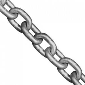
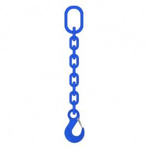
DIN En 818 Short Link Chain for Lifting
DIN En 818 Short Link Chain for Lifting
Category
Lifting and lashing, chain, short link chain, round link chain lifting, Grade 80 chain,G80 chain, chain sling, sling chains, DIN 818-2 medium tolerance chain for chain slings Grade 8, alloy steel chain
Application
Lifting and lashing, loads lifting, loads binding


SCIC Grade 80 (G80) chains for lifting are made as per EN 818-2 standards, with nickel chromium molybdenum manganese alloy steel per DIN 17115 standards; well designed / monitored welding & heat-treatment ensure chains mechanical properties including test force, breaking force, elongation & hardness.
Figure 1: Grade 80 chain link dimensions

Table 1: Grade 80 (G80) chain dimensions, EN 818-2
|
diameter |
pitch |
width |
unit weight |
|||
|
nominal |
tolerance |
p (mm) |
tolerance |
inner W1 |
outer W2 |
|
|
6 |
± 0.24 |
18 |
± 0.5 |
7.8 |
22.2 |
0.8 |
|
7 |
± 0.28 |
21 |
± 0.6 |
9.1 |
25.9 |
1.1 |
|
8 |
± 0.32 |
24 |
± 0.7 |
10.4 |
29.6 |
1.4 |
|
10 |
± 0.4 |
30 |
± 0.9 |
13 |
37 |
2.2 |
|
13 |
± 0.52 |
39 |
± 1.2 |
16.9 |
48.1 |
4.1 |
|
16 |
± 0.64 |
48 |
± 1.4 |
20.8 |
59.2 |
6.2 |
|
18 |
± 0.9 |
54 |
± 1.6 |
23.4 |
66.6 |
8 |
|
19 |
± 1 |
57 |
± 1.7 |
24.7 |
70.3 |
9 |
|
20 |
± 1 |
60 |
± 1.8 |
26 |
74 |
9.9 |
|
22 |
± 1.1 |
66 |
± 2.0 |
28.6 |
81.4 |
12 |
|
23 |
± 1.2 |
69 |
± 2.1 |
29.9 |
85.1 |
13.1 |
|
24 |
± 1.2 |
72 |
± 2.1 |
30 |
84 |
14.5 |
|
25 |
± 1.3 |
75 |
± 2.2 |
32.5 |
92.5 |
15.6 |
|
26 |
± 1.3 |
78 |
± 2.3 |
33.8 |
96.2 |
16.8 |
|
28 |
± 1.4 |
84 |
± 2.5 |
36.4 |
104 |
19.5 |
|
30 |
± 1.5 |
90 |
± 2.7 |
37.5 |
105 |
22.1 |
|
32 |
± 1.6 |
96 |
± 2.9 |
41.6 |
118 |
25.4 |
|
36 |
± 1.8 |
108 |
± 3.2 |
46.8 |
133 |
32.1 |
|
38 |
± 1.9 |
114 |
± 3.4 |
49.4 |
140.6 |
35.8 |
|
40 |
± 2 |
120 |
± 4.0 |
52 |
148 |
39.7 |
|
45 |
± 2.3 |
135 |
± 4.0 |
58.5 |
167 |
52.2 |
|
48 |
± 2.4 |
144 |
± 4.3 |
62.4 |
177.6 |
57.2 |
|
50 |
± 2.6 |
150 |
± 4.5 |
65 |
185 |
62 |
Table 2: Grade 80 (G80) chain mechanical properties, EN 818-2
|
diameter |
working load limit |
manufacturing proof force |
min. breaking force |
|
6 |
1.12 |
28.3 |
45.2 |
|
7 |
1.5 |
38.5 |
61.6 |
|
8 |
2 |
50.3 |
80.4 |
|
10 |
3.15 |
78.5 |
126 |
|
13 |
5.3 |
133 |
212 |
|
16 |
8 |
201 |
322 |
|
18 |
10 |
254 |
407 |
|
19 |
11.2 |
284 |
454 |
|
20 |
12.5 |
314 |
503 |
|
22 |
15 |
380 |
608 |
|
23 |
16 |
415 |
665 |
|
24 |
18 |
452 |
723 |
|
25 |
20 |
491 |
785 |
|
26 |
21.2 |
531 |
850 |
|
28 |
25 |
616 |
985 |
|
30 |
28 |
706 |
1130 |
|
32 |
31.5 |
804 |
1290 |
|
36 |
40 |
1020 |
1630 |
|
38 |
45 |
1130 |
1810 |
|
40 |
50 |
1260 |
2010 |
|
45 |
63 |
1590 |
2540 |
|
48 |
72 |
1800 |
2890 |
|
50 |
78.5 |
1963 |
3140 |
|
notes: total ultimate elongation at breaking force is min. 20%; |
|||
| changes of Working Load Limit in relation to temperature | |
| Temperature (°C) | WLL % |
| -40 to 200 | 100% |
| 200 to 300 | 90% |
| 300 to 400 | 75% |
| over 400 | unacceptable |


